Modifications to CE-QUAL-W2 -- Blending Water From Multiple Reservoir
Outlets to Meet a Downstream Temperature Target
As part of a modeling study of Henry Hagg
Lake in northwestern Oregon, modifications were made to the water-quality
model CE-QUAL-W2 to enable it to blend withdrawals from more than one
reservoir outlet, and set the depth of any adjustable-depth outlets, in
order to meet a user-specified time series of target temperatures for the
released water. In this way, the model can be used to:
- assess whether certain downstream temperature targets can be met
under various structural and operational scenarios,
- assess the effects of using different types of outlets, either
singly or in combination, and
- assess the effects of specifying different temperature targets,
among other things. Some of these objectives, such as using multiple fixed
outlets to meet a downstream temperature target, could have been accomplished
with the model previously, but only by running the model multiple times
and iterating on the flow rates from each outlet. The changes added by the
USGS modeling team allow these tasks to be accomplished in a single model
run, because the necessary operational changes are done automatically.
The Details
Several additions were made to the model in order to implement this new
ability to blend withdrawals from multiple outlets. The most important
of these changes are:
- Each withdrawal is now given a user-specified "bottom elevation
limit," corresponding to the lowest elevation from which that
outlet can withdraw water. This simulates any physical limits of
an outlet structure. If the water surface drops below this level,
the outlet is dry and no water can be withdrawn from that outlet.
- Each withdrawal now must be classified by the model user as either a
fixed-elevation outlet, a "floating" outlet, or a
sliding-gate outlet, as roughly illustrated in the following figure:
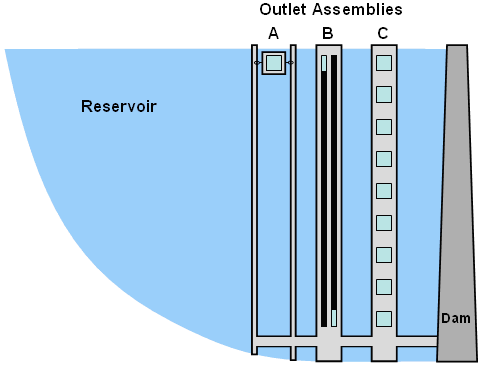
Figure 1. Diagram of several assemblies
of potential CE-QUAL-W2 outlet types. Assembly A contains
one "floating" outlet. Assembly B contains two
adjustable-elevation, or sliding-gate, outlets whose openings
happen to be positioned near the top and bottom of the reservoir.
Assembly C contains nine fixed-elevation outlets. These are the
three types of outlets (floating, sliding-gate, and fixed-elevation)
recognized by the new blending subroutine in CE-QUAL-W2.
Fixed-elevation outlets have an unchanging centerline outlet
elevation. Floating outlets are structures that may stretch
the limits of modern engineering, but are nevertheless useful to
imagine in a modeling exercise; in the model, their centerline outlet
elevation is always set to 1.5 meters below the water surface, unless
the water surface drops below the outlet's bottom elevation limit.
Sliding-gate outlets have a variable outlet elevation, adjusted by
the model, that ranges between the outlet's bottom elevation limit
and the water surface.
- Each withdrawal is assigned to a "withdrawal group"
for modeling purposes. A total withdrawal flow rate is assigned by
the user to each group rather than to each individual withdrawal.
Flows from each withdrawal in a group are adjusted by the model to
match the total withdrawal flow rate for the group. If a group is
assigned more than one withdrawal, or if one of the withdrawals is
a sliding-gate outlet, then it is assumed that the user wishes to
match a downstream temperature target. In that case, the group is
assigned a user-specified time series of target water temperatures.
The model then attempts to blend water from the various outlets in
that group and set the elevation of any variable-elevation outlets
in that group to meet the target water temperature.
- To simulate a situation in which dam operators must make decisions
about the blending of flows from different outlets, the model only
adjusts the blending of flows a user-specified number of times
per day. For example, in a model simulation in which water from two
fixed-elevation outlets is blended to meet a specified temperature
target, the total amount of water withdrawn from the two outlets is
set by the user in the normal manner. The model determines how much
of that total to withdraw from each of the two outlets, in an attempt
to match the target temperature. The user, however, specifies how
many times per day and at what time of day the model can make its
blending adjustment. The model was set up this way to simulate
the fact that these adjustments may be done manually and practical
reasons may preclude frequent adjustments. For the same reasons, the
model also allows the user to give the dam operator the weekend off,
in which case no blending adjustments are made on Saturday or Sunday.
(A day-of-week function was added for this calculation.)
- If more than two withdrawals are assigned to the same withdrawal
group, and more than two of those outlets are below the water
surface, then the model applies a set of rules to determine which
two outlets to use. All other outlets in the group are turned off.
When more than two outlets are available, multiple solutions to
the blending problem can be calculated; by using only two outlets,
the solution becomes straightforward. The following rules are used
to determine which outlets to use and which ones to close:
- In general, the highest and lowest outlets that are
"wet" are used. The rest of the rules are an attempt
to enforce this rule and maintain a maximum amount of flexibility
to access water through as much of the water column as possible.
- Sliding gates are preferred over floating outlets because they
are more flexible in accessing water with different temperatures.
- Fixed outlets are preferred over floating outlets when a
sliding-gate outlet is present.
- A floating or sliding-gate outlet is preferred over the highest
of two fixed outlets.
- Only one floating outlet is ever necessary. Given any other
type of outlet, only one floater will ever be considered for use.
- The lowest fixed outlet is preferred when the other outlet is
either a floater or a slider.
- A sliding-gate outlet is preferred over another sliding-gate
outlet if its bottom elevation limit is lower.
- When two sliding-gate outlets are present, a fixed outlet is
preferred over the shorter slider only if the fixed outlet is
lower than the bottom elevation limits of both sliders.
- The depth of the opening of a sliding-gate outlet is set by the
model in response to a need to access water of a certain temperature.
If a sliding gate is used by itself, the model will set its
elevation at the point in the water column that best matches the
target temperature. If a sliding-gate outlet is one of a pair of
outlets being blended to meet a target temperature, the sliding
gate is set either near the water surface (1.5 meters depth),
or deep in the lake, 1 meter above its bottom elevation limit,
depending on whether the target temperature is warmer or colder
than the water available to the other outlet.
When flows from two outlets are blended to meet a target temperature,
determining the flow from each outlet is a straightforward calculation.
The total release rate from the withdrawal group is known because it was set
by the user in the model's withdrawal flow file. The target temperature also
is known. If more than two outlets are available within a withdrawal group,
the model's rules, just described above in bullet 5, are used to select
the two active outlets. The depth of each outlet is known, and therefore
the simulated water temperature in the lake at the depth of each outlet
also is known. The flows in each outlet, then, are calculated using the
following equations. Conservation of energy requires that:
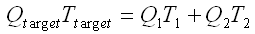 (1)
(1)
where Qtarget is the total release rate, Ttarget
is the target temperature, Q1 and T1 are the flow
and temperature associated with the first outlet, and Q2 and
T2 are the flow and temperature associated with the second outlet.
Conservation of mass requires that:
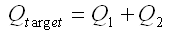 (2)
(2)
Determining the value of Q1, therefore, is a simple matter
of substituting Q2 with (Qtarget - Q1)
and solving for Q1, which leaves:
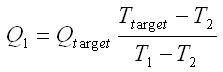 (3)
(3)
Once Q1 is found, the value of Q2 is determined
through application of equation 2. Note that equation 3 only applies when
the target temperature is between the temperatures at the two selected
outlets; this is why the outlet selection rules outlined above were crafted
to select the two outlets that can draw water from as high and as low in
the water column as possible, thus maximizing the available temperature
difference (T1-T2).
If the target temperature is greater or less than both of the outlet
temperatures, the model assigns all of the flow to the outlet having
the temperature closest to the target temperature. If the two outlet
temperatures are identical, then flow is split equally between the two
outlets only if those temperatures also equal the target temperature;
otherwise, a higher target temperature results in all of the flow being
assigned to the higher outlet while a lower target temperature results in
all of the flow being assigned to the lower outlet.
For more details on how the model implements this blending strategy,
the ultimate source of information is the model's source code. A package
containing the source code, a compiled executable for Windows, and some
relevant notes is available for
download [ZIP, 779 Kb]. More information on how these modifications have
been used to assess a potential dam raise at Henry Hagg Lake in northwestern
Oregon is available from the project website.
Note that the model code also implements a set of "avoidance"
algorithms in which "avoidance rules" are set by the user and
consulted by the model when making decisions concerning which outlets to
choose for blending. For example, the user could tell the model to avoid
withdrawing any water where the dissolved oxygen concentration is less
than a certain concentration, and/or where the ammonia concentration
exceeds some concentration. (No avoidance rules were used in the Hagg
Lake model scenarios, though they may be used in the future.) At this
point, the avoidance algorithms are fairly simple and could be made much
more complex.
In addition to the algorithms that take care of the blending details,
new output options were added to the model that aid in documenting how the
blending was done. Such output includes the actual flow rate from each
of the withdrawals involved in blending, their elevation, and the layers
in the model from which the water ultimately was withdrawn.
A summary of the model modifications and their application to an
expanded Hagg Lake is documented in the following report:
Rounds, S.A. and Sullivan, A.B., 2006, Development and
use of new routines in CE-QUAL-W2 to blend water from multiple reservoir
outlets to meet downstream temperature targets, in Proceedings of
the Third Federal Interagency Hydrologic Modeling Conference, April 2-6,
2006, Reno, NV: Subcommittee on Hydrology of the Interagency Advisory
Committee on Water Information, ISBN 0-9779007-0-3.
(full text
[PDF, 198 Kbytes])
-
 Download reports:
- - Henry Hagg Lake
model construction & calibration
- Henry Hagg Lake
model scenarios
- Modifications to
CE-QUAL-W2 [PDF, 198 Kb]
-
Download the model with the new subroutine:
- - Source code, compiled program,
and notes [ZIP, 779 Kb]
Questions? Comments? For more information about this project,
contact:
Erin Leahy
eleahy@usgs.gov
Oregon Water Science Center Home page
Oregon Water Science Center Hydrologic Studies page
Tualatin Water Quality Assessment page
Henry Hagg Lake Water Quality Model page
Henry Hagg Lake Model Scenarios page
